DVA-kit met een intelligente aandrijfregelaar De elektronisch instelbare pomp met constant debiet van HYDAC KineSys
Eenvoudige drukregeling: vertrouw op de HYDAC-aandrijftechniek voor uw perfecte oplossing en ontdek onze voorgemonteerde, geïnspecteerde en vooraf ingestelde druktoevoereenheid. Voor veelzijdig gebruik overal waar constante druktoevoer of variabele drukken nodig zijn tijdens de machinecyclus.
Minimaal vermogensverlies door functioneel geoptimaliseerde aandrijfoplossingen van HYDAC
Optimale aandrijftechniek voor uw allorund-zorgeloos-pakket: laat u nu adviseren over uw op maat gemaakte snelheidsgeregelde aandrijfoplossing.
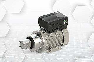
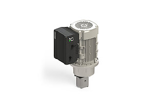
Onze oplossing: HYDAC DVA-kit met een intelligente aandrijfregelaarHet perfecte voorbeeld van symbiose tussen hydrauliek en elektrotechniek
Als Plug & Play-eenheid maakt onze compacte aandrijving met een op de motor gemonteerde regelaar een hydraulische druktoevoer met variabele snelheid mogelijk voor uw toepassingen met een vermogen van 0,55 kW tot 22 kW. De voorgemonteerde, geïnspecteerde en vooraf ingestelde intelligente druktoevoereenheid is voor veelzijdig gebruik overal waar druk moet worden geregeld. De parametrisering van de aandrijfregelaar wordt op uw systeem afgestemd – ongeacht het takenpakket. Een boost-functie kan bijvoorbeeld worden gebruikt voor kortstondige hogere debietvereisten in uw installatie. Bovendien kan met de op de motor gemonteerde regelaar bijna elk hydraulisch aggregaat achteraf worden ingebouwd - er is geen schakelkast nodig.
Technische informatie:
- Asynchrone motor
- Robuuste hydraulische tandwielpomp
- Intelligente aandrijfregelaar met besturingscircuits, netwerken en veiligheidsfuncties zoals STO
- Breed ingangsspanningsbereik
- 3x 400 V (360 tot 480 V)
- 1x 230 V (180 tot 250 V)
- Verminderde energietoevoer naar het systeem
- Geen schakelkast nodig
HYDAC aandrijftechniek: dit maakt het verschil
Eenvoudige integratie en parametrisering Met HYDAC KineSys kan uw systeem direct worden gebruikt
Wij bieden u een allround-zorgeloos-pakket: HYDAC snelheidsgestuurde aandrijvingen zijn eenvoudig te integreren, intelligente druktoevoereenheden die direct in gebruik kunnen worden genomen – u heeft geen systeemoverkoepelende expertise in hydrauliek, elektriciteit en besturingstechniek nodig. Het is ook niet nodig om afzonderlijke componenten te monteren. Dankzij de vast op de motorpompgroep gemonteerde aandrijfregelaar moet er ook geen schakelkast worden geïnstalleerd. Zo worden mogelijke foutenbronnen bij de inbedrijfname vermeden. Het interdisciplinaire HYDAC KineSys-team van hydraulische ingenieurs, werktuigbouwkundigen, elektrotechnici en automatiseringsspecialisten brengt alle puzzelstukjes bij elkaar.
Verminderde complexiteit Eenvoudige aandrijftechniek voor meer efficiëntie
Dankzij onze eenvoudige techniek kunnen alle sensoren en aandrijfdetails via een communicatie-interface op de regelaar in een netwerk met een besturingssysteem worden opgenomen - de hiervoor benodigde sensoren en het besturingssysteem zijn al elektrisch aangesloten en gesynchroniseerd. Dit betekent dat uw systeem zonder extra expertise direct in gebruik kan worden genomen. De foutcode in platte tekst bij de HYDAC aandrijfregelaars maakt ook eenvoudige probleemoplossing en foutanalyse mogelijk. Maar dat is nog niet alles: dankzij de voorgemonteerde en vooraf ingestelde eenheid van motor en aandrijfregelaar is ook een draaiveldtest niet meer nodig. Dit betekent dat het systeemgedrag onafhankelijk is van de netfrequentie. De DVA-kit werkt overal op dezelfde manier: constante hydraulische prestaties wereldwijd.
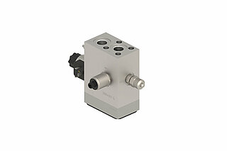
HYDAC hydraulische modules voor frequentieregelaarsKies daarom voor een DVA-Kit met op maat gemaakte hydraulische blokken
HYDAC frequentieregelaar-oplossingen kunnen worden gecombineerd met verschillende hydraulische modules voor voorgeconfigureerde basisfuncties, waaronder sensoren en drukbegrenzing.
Vertrouwen op hydraulische modules voor pompen met frequentieregelaar van HYDAC is de moeite waard:
DVA-kit zonder hydraulisch blok voor pompen met frequentieregelaar
Als u een DVA-kit gebruikt zonder een geschikt afgestemd hydraulisch blok, moet u zorgen voor verdere integraties. Dit betekent dat de volgende taken nog moeten worden voltooid en in aanmerking moeten worden genomen:
- De voedingsspanning aansluiten
- De sensorleidingen aansluiten
- De sensoren synchroniseren met de aandrijfregelaar
De volgende vragen moeten worden beantwoord:
- Waar moet de druksensor worden aangesloten?
- Wie synchroniseert de aangesloten druksensor met betrekking tot signaaltype, signaalniveau en ingangsklem in de aandrijfregelaar?
- Wie past de procesbesturing aan?
DVA-kit met hydraulisch blok voor pompen met frequentieregelaar
Als u een voorgeconfigureerd basisvoedingsblok voor de DVA-kit selecteert, wordt integratie voor u nog eenvoudiger. Dit komt omdat alles op elkaar is afgestemd en gesynchroniseerd. Het resultaat:
- De juiste druksensor is geïntegreerd in het hydraulisch blok en correct gecodeerd in de regelaar.
- De elektrische aansluiting van de sensorleiding is door voorgemonteerde connectoren eenvoudig en veilig.
- U ontvangt ook stapsgewijze instructies voor de inbedrijfname.
Het enige wat u hoeft te doen is de volgende vragen te beantwoorden:
- Waar komt de streefwaarde vandaan?
- Wie sluit de toevoerleiding aan?

FAQ
What is a variable-speed drive?
KineSys variable-speed drives (DVA) are the perfect example of symbiosis between hydraulics and electronics. Thanks to the integrated closed-loop control, the drive motor can be switched on and controlled according to requirements. This results in major potential for energy savings, as only the amount of energy that is actually needed is made available. This means that energy savings of up to 70 % can be achieved, depending on the machine cycle. The condition-optimised adjustment of the KineSys solution reduces the power dissipation to a minimum. It also drastically reduces the complexity on the hydraulic side.
What is meant by closed-loop control?
Closed-loop control circuits
- A control circuit is the self-contained sequence of actions for influencing a physical variable in a technical system or other type of system.
Speed control
- If the general control circuit's system is transferred to the control types used in hydraulics, the following block diagram for speed control is obtained.
- The difference between the target value and actual speed is transferred to the frequency inverter. This then controls the motor so that the control difference (in our example, the speed deviation) is as close to zero as possible.
Pressure control
- This analogy can also be applied to pressure control. The target and actual pressure difference determines the control of the motor. The actual physical pressure variable is determined by a sensor within the fluid and in turn serves as a reference variable for the controller.
Accumulator charging mode
- The accumulator charging mode is a special pressure control application. The underlying controller structure is identical to the figure above.
- If the desired target pressure is reached and there is no decrease in hydraulic power, the drive runs at minimum speed to ensure continuous lubrication of the hydraulic pump. After an adjustable period of time (ΔTimeHysteresis), the drive is switched off completely. If the actual measured pressure value falls below the difference between the target pressure value and ΔPressure hysteresis, the drive switches back on and automatically switches to pressure control. The greatest possible energy savings can be achieved with this operating mode.
What is a (standard) parameterisation?
Parameterisation
Parameterisation means providing a program with variables that control the process.
This also applies to the parameterisation function of our drive controllers. The various parameters are used to define functional variables such as:
- Minimum and maximum speeds
- Control types
- Processing digital and analogue input and output signals
- Bus system interfaces
etc.
Standard parameterisations
With our many years of experience with a wide variety of applications, we have defined standards that fully cover most use cases. Adaptations to your system are of course taken into account for every product that we deliver.
What are the most important parameters for speed control?
Speed control
Below you will find the most important parameters that are present when a drive controller with speed control is supplied to a customer.
- Customer speed target value on analogue input 2
- Analogue input 1 for pressure sensor (no effect on speed control)
- Drive enabling via digital input 1
- Acknowledgement of pending errors via digital input 4
| Parameter number | Description | Value | Unit |
| 1,020 | Minimum frequency | 25 | Hz |
| 1,021 | Maximum frequency | 100 | Hz |
| 1,050 | Braking time 1 | 0.1 | s |
| 1,051 | Run-up time 1 | 0.1 | s |
| 1,100 | Operating mode | Frequency setting mode | - |
| 1,130 | Target value source | Analogue input 2 (0-10 V) | - |
| 1,131 | Software release | Digital input 1 (24 V) | - |
| 1,150 | Direction of rotation | Only left | - |
| 1,180 | Acknowledgement function | Digital input 4 (24 V) | - |
What are the most important parameters for pressure control?
Pressure control
Below you will find the most important parameters that are present when a drive controller with pressure control is supplied to a customer.
- PID process controller for pressure control
- Specification of the P and I components of the controller
- Target value specification by the customer via analogue input 2
- Drive enabling via digital input 1
- Acknowledgement of pending errors via digital input 4
| Parameter number | Description | Value | Unit |
| 1,020 | Minimum frequency | 25 | Hz |
| 1,021 | Maximum frequency | 100 | Hz |
| 1,050 | Braking time 1 | 0.1 | s |
| 1,051 | Run-up time 1 | 0.1 | s |
| 1,100 | Operating mode | PID process controller | - |
| 1,130 | Target value source | Analogue input 2 (0-10 V) | - |
| 1,131 | Software release | Digital input 1 (24 V) | - |
| 1,150 | Direction of rotation | Only left | - |
| 1,180 | Acknowledgement function | Digital input 4 (24 V) | - |
| 3,050 | PID-P amplification | 1 | 1 |
| 3,051 | PID-I amplification | 1 | 1/s |
What are the most important parameters for the accumulator charging mode?
Accumulator charging mode
Below you will find the most important parameters that are present when a drive controller with the accumulator charging mode is supplied to a customer.
- PID process controller for pressure control
- Specification of the P and I components of the controller
- Target value specification by the customer via analogue input 2
- Drive enabling via digital input 1
- Acknowledgement of pending errors via digital input 4
| Parameter number | Description | Value | Unit |
| 1,020 | Minimum frequency | 25 | Hz |
| 1,021 | Maximum frequency | 100 | Hz |
| 1,050 | Braking time 1 | 0.1 | s |
| 1,051 | Run-up time 1 | 0.1 | s |
| 1,100 | Operating mode | PID process controller | - |
| 1,130 | Target value source | Analogue input 2 (0-10 V) | - |
| 1,131 | Software release | Digital input 1 (24 V) | - |
| 1,150 | Direction of rotation | Only left | - |
| 1,180 | Acknowledgement function | Digital input 4 (24 V) | - |
| 3,050 | PID-P amplification | 1 | 1 |
| 3,051 | PID-I amplification | 1 | 1/s |
Accumulator charging mode
- Pressure value as actual value of the PID controller on analogue input 1 (already wired at the factory)
- Standby time = switch-off time after reaching the target pressure + minimum speed
- Standby hysteresis = switch-on and switch-off thresholds in relation to the target pressure
| Parameter number | Description | Value |
| 3,060 | PID actual value | Analogue input 1 (0-10 V) |
| 3,070 | PID standby time | 0.01 s |
| 3,071 | PID standby hysteresis | 10 % |
What process data is provided in the optional fieldbus system?
Optional fieldbus system
If the drive controller is ordered from KineSys with the "Fieldbus" option, the following process data is provided for reading and writing as standard. Further information can be found in the documentation for the particular bus system.
| Parameter number | Description | Value | Unit |
| Not parameterisable | Process data Out 1 | Status word | - |
| Not parameterisable | Process data Out 2 | Actual frequency | Hz |
| 6,080 | Process data Out 3 | Motor voltage | V |
| 6,081 | Process data Out 4 | Motor current | A |
| 6,082 | Process data Out 5 | Supply voltage | V |
| 6,083 | Process data Out 6 | Frequency target value | Hz |
| 6,084 | Process data Out 7 | Digital inputs bit-coded | - |
| 6,085 | Process data Out 8 | Analogue input 1 | V |
| 6,086 | Process data Out 9 | Error word 1 | - |
| 6,087 | Process data Out 10 | Error word 2 | - |
| Not parameterisable | Process data In 1 | Control word | - |
| Not parameterisable | Process data In 2 | Target value | % |
| 6,110 | Process data In 3 | Digital outputs - relay | - |
| 6,111 | Process data In 4 | Analogue output 1 | V |
| 6,112 | Process data In 5 | Customer spec. PLC input variable 1 | - |
| 6,113 | Process data In 6 | Customer spec. PLC input variable 2 | - |
What do circuit diagrams for motor-mounted frequency inverters look like?
Circuit diagram
The two circuit diagrams for motor-mounted frequency inverters from KineSys with and without the STO function (Safe-Torque-Off) are shown below. Controlling a valve via digital output and an optocoupler is an option and is not included in the standard scope of delivery.
