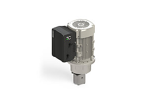
DVA Kit with an intelligent drive controller The electronically adjustable fixed displacement pump from HYDAC KineSys
Simple pressure control: rely on HYDAC drive technology for your perfect solution and discover our pre-assembled, inspected and pre-set pressure supply unit. For versatile use wherever constant pressure supply or variable pressures are needed during the machine cycle.
Minimal power dissipation thanks to function-optimized drive solutions from HYDAC
Optimal drive technology for your all-round carefree package: get advice on your custom-fit speed-controlled drive solution now.
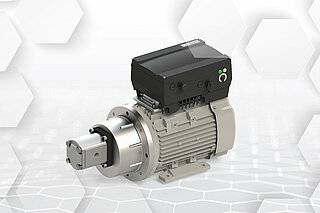
Our solution: HYDAC DVA Kit with an intelligent drive controllerThe perfect example of symbiosis between hydraulics and electrical engineering
As a plug & play unit, our compact drive with a motor-mounted drive controller enables variable-speed, hydraulic pressure supply for your applications with a power of 0.55 kW to 22 kW. The pre-assembled, inspected and pre-set intelligent pressure supply unit is for versatile use wherever pressure needs to be controlled. The drive controller parameterization is tailored to your system – whatever the range of tasks include. For example, a boost function can be used for short-term higher flow rate requirements in your system. In addition, the motor-mounted drive controller allows almost any hydraulic unit to be retrofitted - as a switch cabinet is not required.
Technical information:
- Asynchronous motor
- Robust hydraulic gear pump
- Intelligent drive controller with control circuits, networking and safety functions such as STO
- Wide input voltage range
- 3x 400 V (360 to 480 V)
- 1x 230 V (180 to 250 V)
- Reduced energy input into the system
- No switch cabinet needed
HYDAC drive technology: this makes the difference
Simple integration & parameterization With HYDAC KineSys, your system can be used straightaway
We offer you an all-round carefree package: HYDAC speed-controlled drives are easy-to-integrate, intelligent pressure supply units which can be put into operation immediately – you don't need any cross-system expertise in hydraulics, electrics and control technology. There is also no need to assemble individual components. Thanks to the drive controller permanently mounted on the motor-pump group, there is also no need for switch cabinet installation. This means that possible sources of error during commissioning are avoided. Our interdisciplinary HYDAC KineSys Team of hydraulic engineers, mechanical engineers, electrical engineers and automation specialists bring all the pieces of the puzzle together.
Reduced complexity Straightforward drive technology for more efficiency
Thanks to our straightforward technology, all sensors and drive details can be networked with a control system via a communication interface on the drive controller - the sensors and control system required for this are already electrically connected and synchronized. This means that your system can be used straightaway without any additional expertise. The plain text error code with HYDAC drive controllers also enables easy troubleshooting and error analysis. But that's not all: thanks to the pre-assembled and pre-set unit made up of a motor and drive controller, a rotary field test is also no longer necessary. This means that the system behavior is independent of the supply frequency. The DVA Kit operates in the same way everywhere: constant hydraulic performance worldwide.
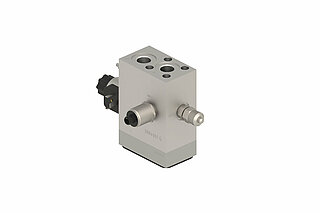
HYDAC hydraulic modules for variable-speed drivesThis is why you should opt for a DVA Kit with tailored hydraulic blocks
HYDAC variable-speed drive solutions can be combined with various hydraulic modules for preconfigured basic functions, including sensors and pressure limiting.
Relying on hydraulic modules for variable-speed pumps from HYDAC is worth your while:
DVA Kit without hydraulic block for variable-speed pumps
If you use a DVA kit without a suitably matched hydraulic block, you have to take care of additional integrations. This means that the following tasks will still need to be completed and taken into account:
- Connecting the supply voltage
- Connecting the sensor lines
- Synchronizing the sensors with the drive controller
The following questions must be answered:
- Where does the pressure sensor need to be connected?
- Who will synchronize the connected pressure sensor with regard to signal type, signal level and input terminal in the drive controller?
- Who will adjust the process controller?
DVA Kit with hydraulic block for variable-speed pumps
If you select a preconfigured basic supply block for the DVA kit, integration is even easier for you. This is because everything is coordinated with each other and synchronized. As a result:
- The right pressure sensor is integrated into the hydraulic block and appropriately coded in the drive controller.
- The electrical connection of the sensor line is simple and safe due to pre-assembled connectors.
- You'll also receive step-by-step instructions for commissioning.
All you have to do is answer the following questions:
- Where does the target value come from?
- Who will connect the supply line?

FAQ
What is a variable-speed drive?
KineSys variable-speed drives (DVA) are the perfect example of symbiosis between hydraulics and electronics. Thanks to the integrated closed-loop control, the drive motor can be switched on and controlled according to requirements. This results in major potential for energy savings, as only the amount of energy that is actually needed is made available. This means that energy savings of up to 70 % can be achieved, depending on the machine cycle. The condition-optimised adjustment of the KineSys solution reduces the power dissipation to a minimum. It also drastically reduces the complexity on the hydraulic side.
What is meant by closed-loop control?
Closed-loop control circuits
- A control circuit is the self-contained sequence of actions for influencing a physical variable in a technical system or other type of system.
Speed control
- If the general control circuit's system is transferred to the control types used in hydraulics, the following block diagram for speed control is obtained.
- The difference between the target value and actual speed is transferred to the frequency inverter. This then controls the motor so that the control difference (in our example, the speed deviation) is as close to zero as possible.
Pressure control
- This analogy can also be applied to pressure control. The target and actual pressure difference determines the control of the motor. The actual physical pressure variable is determined by a sensor within the fluid and in turn serves as a reference variable for the controller.
Accumulator charging mode
- The accumulator charging mode is a special pressure control application. The underlying controller structure is identical to the figure above.
- If the desired target pressure is reached and there is no decrease in hydraulic power, the drive runs at minimum speed to ensure continuous lubrication of the hydraulic pump. After an adjustable period of time (ΔTimeHysteresis), the drive is switched off completely. If the actual measured pressure value falls below the difference between the target pressure value and ΔPressure hysteresis, the drive switches back on and automatically switches to pressure control. The greatest possible energy savings can be achieved with this operating mode.
What is a (standard) parameterisation?
Parameterisation
Parameterisation means providing a program with variables that control the process.
This also applies to the parameterisation function of our drive controllers. The various parameters are used to define functional variables such as:
- Minimum and maximum speeds
- Control types
- Processing digital and analogue input and output signals
- Bus system interfaces
etc.
Standard parameterisations
With our many years of experience with a wide variety of applications, we have defined standards that fully cover most use cases. Adaptations to your system are of course taken into account for every product that we deliver.
What are the most important parameters for speed control?
Speed control
Below you will find the most important parameters that are present when a drive controller with speed control is supplied to a customer.
- Customer speed target value on analogue input 2
- Analogue input 1 for pressure sensor (no effect on speed control)
- Drive enabling via digital input 1
- Acknowledgement of pending errors via digital input 4
| Parameter number | Description | Value | Unit |
| 1,020 | Minimum frequency | 25 | Hz |
| 1,021 | Maximum frequency | 100 | Hz |
| 1,050 | Braking time 1 | 0.1 | s |
| 1,051 | Run-up time 1 | 0.1 | s |
| 1,100 | Operating mode | Frequency setting mode | - |
| 1,130 | Target value source | Analogue input 2 (0-10 V) | - |
| 1,131 | Software release | Digital input 1 (24 V) | - |
| 1,150 | Direction of rotation | Only left | - |
| 1,180 | Acknowledgement function | Digital input 4 (24 V) | - |
What are the most important parameters for pressure control?
Pressure control
Below you will find the most important parameters that are present when a drive controller with pressure control is supplied to a customer.
- PID process controller for pressure control
- Specification of the P and I components of the controller
- Target value specification by the customer via analogue input 2
- Drive enabling via digital input 1
- Acknowledgement of pending errors via digital input 4
| Parameter number | Description | Value | Unit |
| 1,020 | Minimum frequency | 25 | Hz |
| 1,021 | Maximum frequency | 100 | Hz |
| 1,050 | Braking time 1 | 0.1 | s |
| 1,051 | Run-up time 1 | 0.1 | s |
| 1,100 | Operating mode | PID process controller | - |
| 1,130 | Target value source | Analogue input 2 (0-10 V) | - |
| 1,131 | Software release | Digital input 1 (24 V) | - |
| 1,150 | Direction of rotation | Only left | - |
| 1,180 | Acknowledgement function | Digital input 4 (24 V) | - |
| 3,050 | PID-P amplification | 1 | 1 |
| 3,051 | PID-I amplification | 1 | 1/s |
What are the most important parameters for the accumulator charging mode?
Accumulator charging mode
Below you will find the most important parameters that are present when a drive controller with the accumulator charging mode is supplied to a customer.
- PID process controller for pressure control
- Specification of the P and I components of the controller
- Target value specification by the customer via analogue input 2
- Drive enabling via digital input 1
- Acknowledgement of pending errors via digital input 4
| Parameter number | Description | Value | Unit |
| 1,020 | Minimum frequency | 25 | Hz |
| 1,021 | Maximum frequency | 100 | Hz |
| 1,050 | Braking time 1 | 0.1 | s |
| 1,051 | Run-up time 1 | 0.1 | s |
| 1,100 | Operating mode | PID process controller | - |
| 1,130 | Target value source | Analogue input 2 (0-10 V) | - |
| 1,131 | Software release | Digital input 1 (24 V) | - |
| 1,150 | Direction of rotation | Only left | - |
| 1,180 | Acknowledgement function | Digital input 4 (24 V) | - |
| 3,050 | PID-P amplification | 1 | 1 |
| 3,051 | PID-I amplification | 1 | 1/s |
Accumulator charging mode
- Pressure value as actual value of the PID controller on analogue input 1 (already wired at the factory)
- Standby time = switch-off time after reaching the target pressure + minimum speed
- Standby hysteresis = switch-on and switch-off thresholds in relation to the target pressure
| Parameter number | Description | Value |
| 3,060 | PID actual value | Analogue input 1 (0-10 V) |
| 3,070 | PID standby time | 0.01 s |
| 3,071 | PID standby hysteresis | 10 % |
What process data is provided in the optional fieldbus system?
Optional fieldbus system
If the drive controller is ordered from KineSys with the "Fieldbus" option, the following process data is provided for reading and writing as standard. Further information can be found in the documentation for the particular bus system.
| Parameter number | Description | Value | Unit |
| Not parameterisable | Process data Out 1 | Status word | - |
| Not parameterisable | Process data Out 2 | Actual frequency | Hz |
| 6,080 | Process data Out 3 | Motor voltage | V |
| 6,081 | Process data Out 4 | Motor current | A |
| 6,082 | Process data Out 5 | Supply voltage | V |
| 6,083 | Process data Out 6 | Frequency target value | Hz |
| 6,084 | Process data Out 7 | Digital inputs bit-coded | - |
| 6,085 | Process data Out 8 | Analogue input 1 | V |
| 6,086 | Process data Out 9 | Error word 1 | - |
| 6,087 | Process data Out 10 | Error word 2 | - |
| Not parameterisable | Process data In 1 | Control word | - |
| Not parameterisable | Process data In 2 | Target value | % |
| 6,110 | Process data In 3 | Digital outputs - relay | - |
| 6,111 | Process data In 4 | Analogue output 1 | V |
| 6,112 | Process data In 5 | Customer spec. PLC input variable 1 | - |
| 6,113 | Process data In 6 | Customer spec. PLC input variable 2 | - |
What do circuit diagrams for motor-mounted frequency inverters look like?
Circuit diagram
The two circuit diagrams for motor-mounted frequency inverters from KineSys with and without the STO function (Safe-Torque-Off) are shown below. Controlling a valve via digital output and an optocoupler is an option and is not included in the standard scope of delivery.
